Click on picture to
|
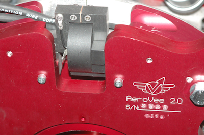
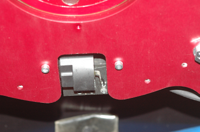
These first two pictures show each magneto, 180º apart. You can’t see the adjusting shim in these pictures, but a thin, 0.010” shim is between the magneto and the magnet. Tighten them down and that is the only adjustment required.
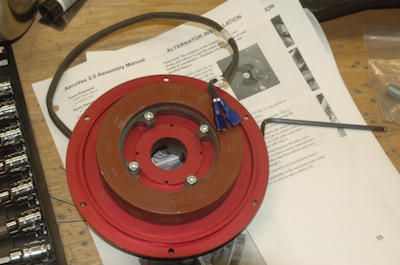
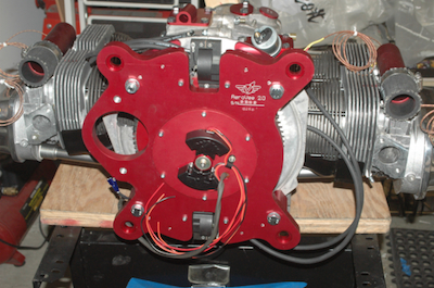
These two pictures show the plate that holds both the alternator stator coils and the electronic ignition triggers. The electronic ignition fires when the little trigger magnets pass by. This little magnet may need to be advanced or retarded slightly so that firing takes place at the same time as the magnetos. Once it is set however, no adjustment will be necessary. The stator coils of course are where the 14 volts of the 20 amp alternator are generated by the passing magnets. The heavy dark wire contains the alternator leads that go to the voltage regulator. All of these components are the stationary halves of each device.
|