Click on a picture to
|
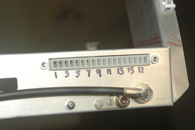
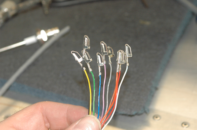
So with every switch wired except one, it was time to make the harnesses for the transponder, Enigma and com. These pictures show the transponder from start to powered up. The first picture shows the back of the tray that holds the transponder. I had to mount this card edge connector first. I numbered the slots for insertion of the pins and then I made the harness. The second picture shows the 10 wire bundle that connects the transponder to the altitude encoder output of the Enigma.
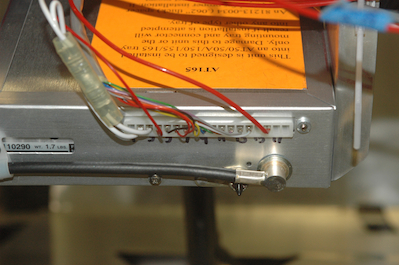
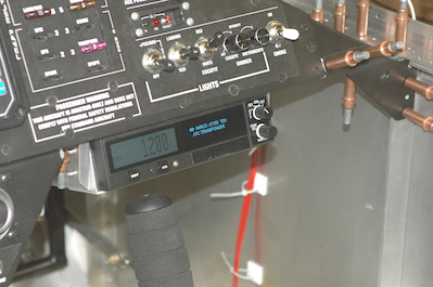
So with every switch wired except one, it was time to make the harnesses for the transponder, Enigma and com. These pictures show the transponder from start to powered up.>The first picture shows the back of the tray that holds the transponder. I had to mount this card edge connector first. I numbered the slots for insertion of the pins and then I made the harness. The second picture shows the 10 wire bundle that connects the transponder to the altitude encoder output of the Enigma. The third picture shows those 10 wires inserted into the connector along with power, dimmer signal wire and two ground wires. At this point I had also attached a D15 connector to the other end to connect the 10 wires to the Enigma but I forgot to take pictures of that process. The last picture shows the transponder powered up in standby mode.
|