Click on picture to
|
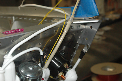
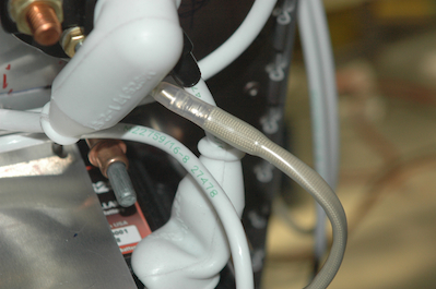
Two more fancy wires in the next two pictures. The slightly gray wires are the leads that will go to the IO Xtndr – now on the other side of the firewall! They are yellow 20 awg wire runs that go from each side of the main power feed from the battery to the battery contactor. I will basically be using this segment of wire as a shunt. The IO Xtndr will measure the voltage drop across this wire and convert that to an amperage value. In this case 20 amps will show up as about 12.5mv signal. The gray segments are fusible links I made up with 24 awg wire. That wire runs from the ring terminal to the butt splice and is covered with a fiberglass silicone sleeve. That is then covered with heat shrink tubing. If a short should develop downstream from these wires, the fusible links will melt in the sleeve breaking the connection.
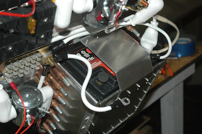
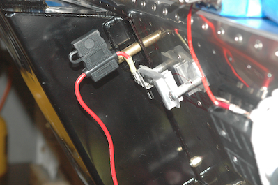
Speaking of shorts. I have been testing all of the devices in stages, and of course, a bunch of these early wires connect to the battery. So instead of removing the battery I have followed a protocol where I disconnect the negative battery lead and cover the post after any tests and before doing any wiring. The last picture shows the DC lead from the voltage regulator. This will run to a large capacitor and relay. Just an inline fuse holder for now.
|