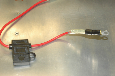
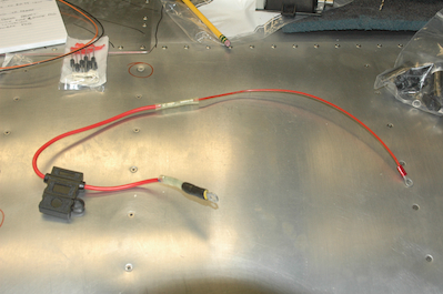
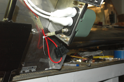
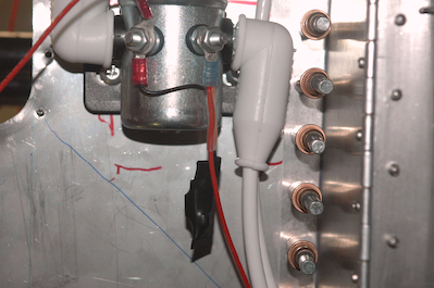
Then add an inline fuse package and butt splice a lead with a ring terminal on it. That ring terminal was temporary for testing and fitting. You can see how it fits in pictures three and four. You will see a lot of tie wraps in the engine compartment. They are all temporary. Any tie wraps this side of the firewall need to be stainless. Also this is hanging loose because it will be supported by the engine mount struts.
The fifth picture shows the final ring terminal in place for this lead. It has the crowbar over voltage unit attached. It is hard to see, but one lead from this unit is paired up with the main lead in the blue ended ring terminal. Then all three wires run through a short segment of heat shrink tubing with the black lead from the crowbar device going to the other post on the contactor. This device will essentially dead short the feed when more than 16.5 v is present on the sense post. That will blow the 2 amp fuse in the inline fuse holder. The diode will prevent a reverse polarity hookup.
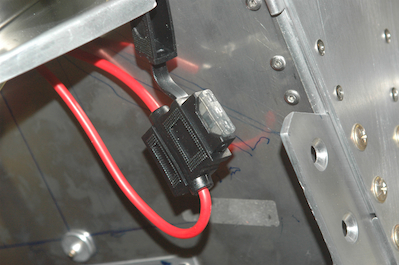
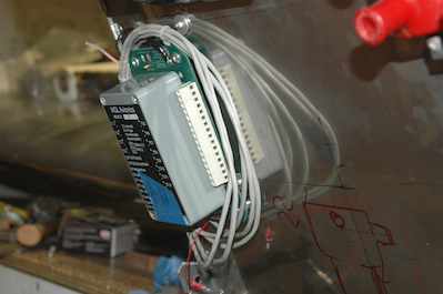
That’s a lot for one little wire to do. The last picture just shows the remounted RDAC.