Click on a picture to
|
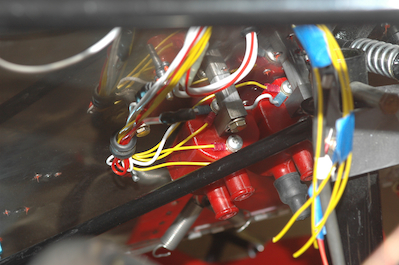
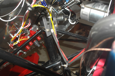
It is getting crowded in the firewall forward area so these first two pictures are hard to explain. They are the in process and fully installed pictures of the alternator and electronic ignition wiring. In the first picture there are four yellow wires coming from the two red ignition coils. These wires have been integrated into an existing wiring bundle. They can also be seen dropping down from above in preparation for connecting them. The second picture shows this area after all the connections have been made. Just above the yellow arc of wires are two blue spade connectors. These are the alternator leads and they are plugged into the voltage regulator. I bought two connectors that double the spades on the voltage regulator and the two blue connectors are each in one of them with along with an open connector. I did this because the RPM indication is picked up from one of these posts by the Enigma. The problem is there is no way to know which one is the correct one. You have a 50/50 chance of picking the correct one. If you don’t you just have to switch them around. These make it easy to switch and not monkey around with the alternator leads again. The yellow wires and the alternator leads then run down to a clamp on the frame to hold them securely and then they route to the back of the engine. The yellow wires are crimped to the orange and red wires coming from the ignition triggers.
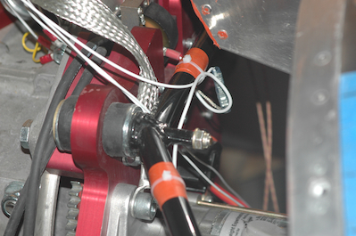
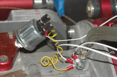
Picture three is of the top magneto wiring and the last picture shows the location of all the engine block grounds. Notice that I substituted a two lead pressure sender for the supplied one lead unit. This mounts into an anodized piece and many people have had problems getting a good ground. This unit has a second stud just for the ground.
|