Click on a picture to
|
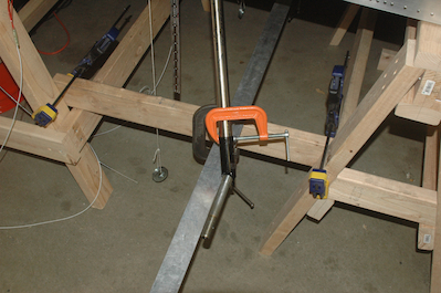
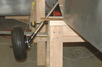
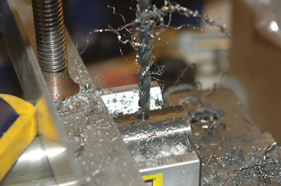
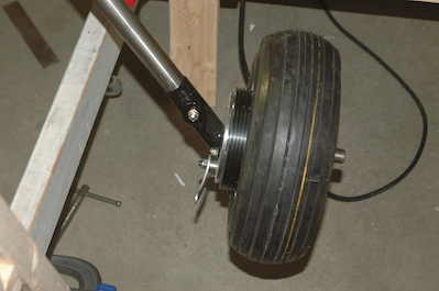
With all of the wheel assembly prep work done it was time to set the toe in and height of the axles. The first picture shows the setup I used. I don’t actually have any pictures of the process but at the point of the picture, I have used a laser level set to the bottom of the scale that is hanging down in the picture. The center of both axles will be adjusted to match this height. You can also see two plumb lines that hang from the same station lines of the left and right fuselage sides. There is a straight edge that has been clamped in front of both axles that is the same distance on each side from the plumb lines. On the inboard side of the axle is a small bushing that comes with the kit that is used in measuring the toe in angle. I raised, lowered and rotated the axle on each leg until the height and toe in measure all came out correctly - (.7°). This angle comes out automatically if you keep the front edge of the axle and the front edge of the supplied bushing the same distance from the straightedge. Then I clamped the axle in place. I did a lot of back and forth and when I was sure both were in the correct spot, I took the same size pilot drill I used on the axle assembly and used that pilot hole as a guide to drill a starting hole in the titanium gear leg. I then drilled out the gear leg and mounted the axles.
|