Click on a picture to
|
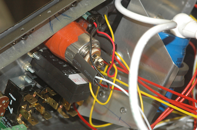
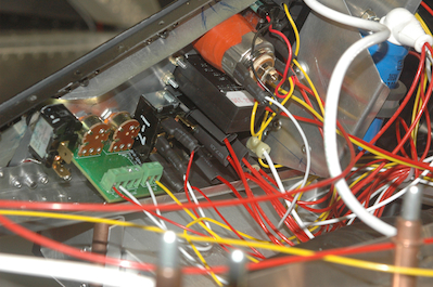
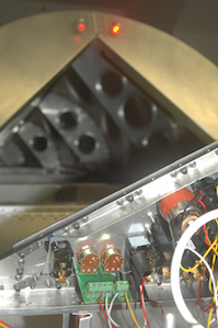
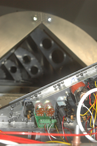
From the left side of the panel to the right. The last remaining power circuit is the AUX POWER outlet. This is a three amp circuit that is connected to the always powered buss and can be used to run a handheld device in the cockpit if needed. The second picture shows the finished lighting circuits all in place. The last two pictures show the red and white cockpit lights connected to the dimmer circuits. The dimmer is the small green PCB with the two variable resistors. Much more wiring to go. I have already started on wiring up the EFIS to the backup battery as well as to the four instruments it powers. I also have to hook up the engine ignition and starting circuits as well as make the transponder and comm. harnesses.
|