Click on picture to
|
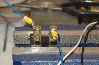
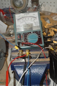
Before getting to the wing hardware, I tested the load needed to support the lights in the left wing. To do that, all the power is fed through a shunt. In this case a 20 amp shunt since that is the output of my alternator. When no current is flowing through the circuit, the voltage measured across the shunt is zero. When there is 20 amps of current flowing in the circuit, the voltage across the shunt is 50 ma. I will hook this up to a generic 50 ma meter that will display from 0 to 100 and serve as a load meter. The load on the meter in the second picture is just after the HID landing light was turned on and shows the large in rush current. It settles down after a few seconds to around 4 amps. With the scale I'm using in the picture, the needle is indicating about 7 amps and just before I hit the shutter on the camera it was at 9.
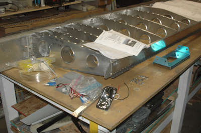
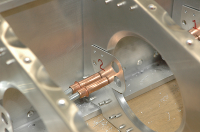
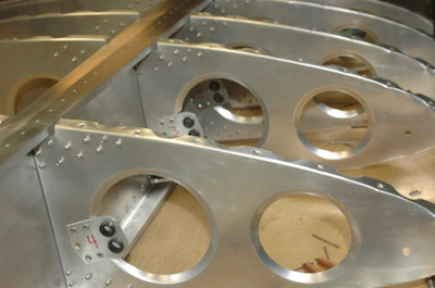
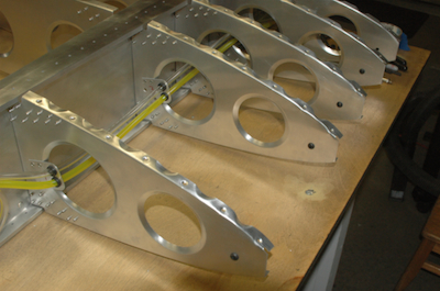
Then on to wing hardware. The first picture shows the lighting, static and pitot hardware needing to be installed. The rest of the pictures show the installation of the pitot and static systems. This was not done on the left wing. The static air pressure line drives the altimeter and the pitot and static pressure lines together drive the airspeed indicator.
|